The first and most straightforward network analysis technique is called the
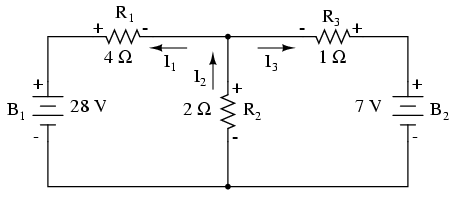
Let's use this circuit to illustrate the method:
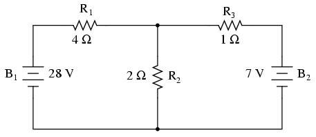
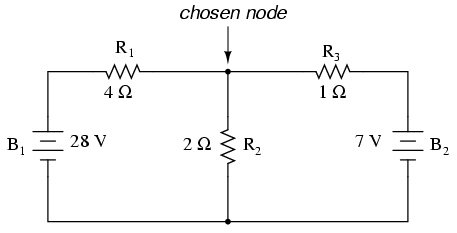
The first step is to choose a node (junction of wires) in the circuit to use as a point of reference for our unknown currents. I'll choose the node joining the right of R1, the top of R2, and the left of R3.
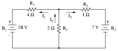
At this node, guess which directions the three wires' currents take, labeling the three currents as I1, I2, and I3, respectively. Bear in mind that these directions of current are speculative at this point. Fortunately, if it turns out that any of our guesses were wrong, we will know when we mathematically solve for the currents (any “wrong” current directions will show up as negative numbers in our solution).
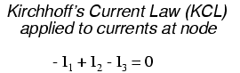
Kirchhoff's Current Law (KCL) tells us that the algebraic sum of currents entering and exiting a node must equal zero, so we can relate these three currents (I1, I2, and I3) to each other in a single equation. For the sake of convention, I'll denote any current entering the node as positive in sign, and any current exiting the node as negative in sign:
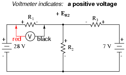
The next step is to label all voltage drop polarities across resistors according to the assumed directions of the currents. Remember that the “upstream” end of a resistor will always be negative, and the “downstream” end of a resistor positive with respect to each other, since electrons are negatively charged:
The battery polarities, of course, remain as they were according to their symbology (short end negative, long end positive). It is OK if the polarity of a resistor's voltage drop doesn't match with the polarity of the nearest battery, so long as the resistor voltage polarity is correctly based on the assumed direction of current through it. In some cases we may discover that current will be forced backwards through a battery, causing this very effect. The important thing to remember here is to base all your resistor polarities and subsequent calculations on the directions of current(s) initially assumed. As stated earlier, if your assumption happens to be incorrect, it will be apparent once the equations have been solved (by means of a negative solution). The magnitude of the solution, however, will still be correct.
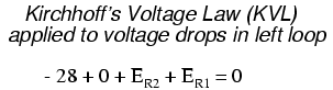
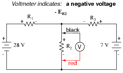
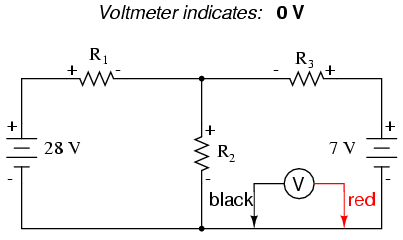
Kirchhoff's Voltage Law (KVL) tells us that the algebraic sum of all voltages in a loop must equal zero, so we can create more equations with current terms (I1, I2, and I3) for our simultaneous equations. To obtain a KVL equation, we must tally voltage drops in a loop of the circuit, as though we were measuring with a real voltmeter. I'll choose to trace the left loop of this circuit first, starting from the upper-left corner and moving counter-clockwise (the choice of starting points and directions is arbitrary). The result will look like this:
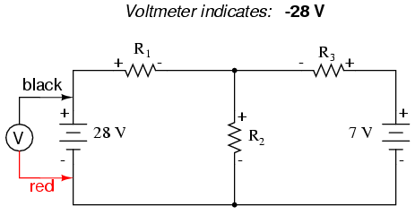
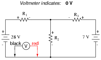
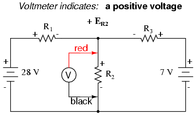
Having completed our trace of the left loop, we add these voltage indications together for a sum of zero:
Of course, we don't yet know what the voltage is across R1 or R2, so we can't insert those values into the equation as numerical figures at this point. However, we do know that all three voltages must algebraically add to zero, so the equation is true. We can go a step further and express the unknown voltages as the product of the corresponding unknown currents (I1 and I2) and their respective resistors, following Ohm's Law (E=IR), as well as eliminate the 0 term:
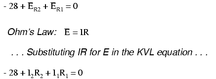
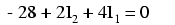
Since we know what the values of all the resistors are in ohms, we can just substitute those figures into the equation to simplify things a bit:
You might be wondering why we went through all the trouble of manipulating this equation from its initial form (-28 + ER2 + ER1). After all, the last two terms are still unknown, so what advantage is there to expressing them in terms of unknown voltages or as unknown currents (multiplied by resistances)? The purpose in doing this is to get the KVL equation expressed using the same unknown variables as the KCL equation, for this is a necessary requirement for any simultaneous equation solution method. To solve for three unknown currents (I1, I2, and I3), we must have three equations relating these three currents (not voltages!) together.
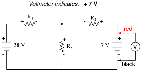
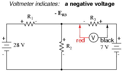
Applying the same steps to the right loop of the circuit (starting at the chosen node and moving counter-clockwise), we get another KVL equation:
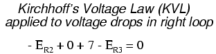
Knowing now that the voltage across each resistor can be and should be expressed as the product of the corresponding current and the (known) resistance of each resistor, we can re-write the equation as such:
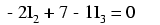
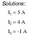
Now we have a mathematical system of three equations (one KCL equation and two KVL equations) and three unknowns:

For some methods of solution (especially any method involving a calculator), it is helpful to express each unknown term in each equation, with any constant value to the right of the equal sign, and with any “unity” terms expressed with an explicit coefficient of 1. Re-writing the equations again, we have:
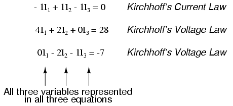
Using whatever solution techniques are available to us, we should arrive at a solution for the three unknown current values:
So, I1 is 5 amps, I2 is 4 amps, and I3 is a negative 1 amp. But what does “negative” current mean? In this case, it means that our assumed direction for I3 was opposite of its real direction. Going back to our original circuit, we can re-draw the current arrow for I3 (and re-draw the polarity of R3's voltage drop to match):
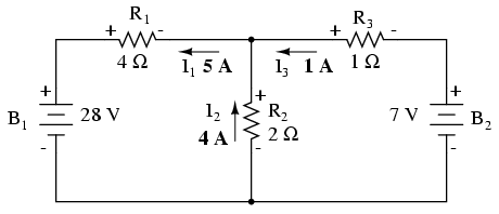
Notice how current is being pushed backwards through battery 2 (electrons flowing “up”) due to the higher voltage of battery 1 (whose current is pointed “down” as it normally would)! Despite the fact that battery B2's polarity is trying to push electrons down in that branch of the circuit, electrons are being forced backwards through it due to the superior voltage of battery B1. Does this mean that the stronger battery will always “win” and the weaker battery always get current forced through it backwards? No! It actually depends on both the batteries' relative voltages and the resistor values in the circuit. The only sure way to determine what's going on is to take the time to mathematically analyze the network.
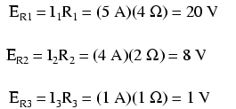
Now that we know the magnitude of all currents in this circuit, we can calculate voltage drops across all resistors with Ohm's Law (E=IR):
Let us now analyze this network using SPICE to verify our voltage figures.[spi] We could analyze current as well with SPICE, but since that requires the insertion of extra components into the circuit, and because we know that if the voltages are all the same and all the resistances are the same, the currents must all be the same, I'll opt for the less complex analysis. Here's a re-drawing of our circuit, complete with node numbers for SPICE to reference:
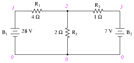
network analysis example
v1 1 0
v2 3 0 dc 7
r1 1 2 4
r2 2 0 2
r3 2 3 1
.dc v1 28 28 1
.print dc v(1,2) v(2,0) v(2,3)
.end
v1            v(1,2)      v(2)        v(2,3)
2.800E+01     2.000E+01   8.000E+00   1.000E+00
Sure enough, the voltage figures all turn out to be the same: 20 volts across R1 (nodes 1 and 2), 8 volts across R2 (nodes 2 and 0), and 1 volt across R3 (nodes 2 and 3). Take note of the signs of all these voltage figures: they're all positive values! SPICE bases its polarities on the order in which nodes are listed, the first node being positive and the second node negative. For example, a figure of positive (+) 20 volts between nodes 1 and 2 means that node 1 is positive with respect to node 2. If the figure had come out negative in the SPICE analysis, we would have known that our actual polarity was “backwards” (node 1 negative with respect to node 2). Checking the node orders in the SPICE listing, we can see that the polarities all match what we determined through the Branch Current method of analysis.
- REVIEW:
- Steps to follow for the “Branch Current” method of analysis:
- (1) Choose a node and assume directions of currents.
- (2) Write a KCL equation relating currents at the node.
- (3) Label resistor voltage drop polarities based on assumed currents.
- (4) Write KVL equations for each loop of the circuit, substituting the product IR for E in each resistor term of the equations.
- (5) Solve for unknown branch currents (simultaneous equations).
- (6) If any solution is negative, then the assumed direction of current for that solution is wrong!
- (7) Solve for voltage drops across all resistors (E=IR).
Share this on your favourite network


0 comments :
Post a Comment