Maximum Power Transfer Theorem Step By Step Procedure/Explanation

The Maximum Power Transfer Theorem is not so much a means of analysis as it is an aid to system design. Simply stated, the maximum amount of power will be dissipated by a load resistance when that load resistance is equal to the Thevenin/Norton resistance of the network supplying the power. If the load resistance is lower or higher than the Thevenin/Norton resistance of the source network, its dissipated power will be less than maximum.
This is essentially what is aimed for in radio transmitter design , where the antenna or transmission line “impedance” is matched to final power amplifier “impedance” for maximum radio frequency power output. Impedance, the overall opposition to AC and DC current, is very similar to resistance, and must be equal between source and load for the greatest amount of power to be transferred to the load. A load impedance that is too high will result in low power output. A load impedance that is too low will not only result in low power output, but possibly overheating of the amplifier due to the power dissipated in its internal (Thevenin or Norton) impedance.
Taking our Thevenin equivalent example circuit, the Maximum Power Transfer Theorem tells us that the load resistance resulting in greatest power dissipation is equal in value to the Thevenin resistance (in this case, 0.8 Ω):

With this value of load resistance, the dissipated power will be 39.2 watts:

If we were to try a lower value for the load resistance (0.5 Ω instead of 0.8 Ω, for example), our power dissipated by the load resistance would decrease:

Power dissipation increased for both the Thevenin resistance and the total circuit, but it decreased for the load resistor. Likewise, if we increase the load resistance (1.1 Ω instead of 0.8 Ω, for example), power dissipation will also be less than it was at 0.8 Ω exactly:

If you were designing a circuit for maximum power dissipation at the load resistance, this theorem would be very useful. Having reduced a network down to a Thevenin voltage and resistance (or Norton current and resistance), you simply set the load resistance equal to that Thevenin or Norton equivalent (or vice versa) to ensure maximum power dissipation at the load. Practical applications of this might include radio transmitter final amplifier stage design (seeking to maximize power delivered to the antenna or transmission line), a grid tied inverter loading a solar array, or electric vehicle design (seeking to maximize power delivered to drive motor).
The Maximum Power Transfer Theorem is not: Maximum power transfer does not coincide with maximum efficiency. Application of The Maximum Power Transfer theorem to AC power distribution will not result in maximum or even high efficiency. The goal of high efficiency is more important for AC power distribution, which dictates a relatively low generator impedance compared to load impedance.
Similar to AC power distribution, high fidelity audio amplifiers are designed for a relatively low output impedance and a relatively high speaker load impedance. As a ratio, "output impdance" : "load impedance" is known as damping factor, typically in the range of 100 to 1000.
Maximum power transfer does not coincide with the goal of lowest noise. For example, the low-level radio frequency amplifier between the antenna and a radio receiver is often designed for lowest possible noise. This often requires a mismatch of the amplifier input impedance to the antenna as compared with that dictated by the maximum power transfer theorem.
  • REVIEW:
  • The Maximum Power Transfer Theorem states that the maximum amount of power will be dissipated by a load resistance if it is equal to the Thevenin or Norton resistance of the network supplying power.
  • The Maximum Power Transfer Theorem does not satisfy the goal of maximum efficiency.

Thevenin-Norton equivalencies Step By Step Procedure/Explanation

Since Thevenin's and Norton's Theorems are two equally valid methods of reducing a complex network down to something simpler to analyze, there must be some way to convert a Thevenin equivalent circuit to a Norton equivalent circuit, and vice versa (just what you were dying to know, right?). Well, the procedure is very simple. .......
You may have noticed that the procedure for calculating Thevenin resistance is identical to the procedure for calculating Norton resistance: remove all power sources and determine resistance between the open load connection points. As such, Thevenin and Norton resistances for the same original network must be equal. Using the example circuits from the last two sections, we can see that the two resistances are indeed equal:..........


Considering the fact that both Thevenin and Norton equivalent circuits are intended to behave the same as the original network in suppling voltage and current to the load resistor (as seen from the perspective of the load connection points), these two equivalent circuits, having been derived from the same original network should behave identically. .......
This means that both Thevenin and Norton equivalent circuits should produce the same voltage across the load terminals with no load resistor attached. With the Thevenin equivalent, the open-circuited voltage would be equal to the Thevenin source voltage (no circuit current present to drop voltage across the series resistor), which is 11.2 volts in this case. With the Norton equivalent circuit, all 14 amps from the Norton current source would have to flow through the 0.8 Ω Norton resistance, producing the exact same voltage, 11.2 volts (E=IR). Thus, we can say that the Thevenin voltage is equal to the Norton current times the Norton resistance: .......

So, if we wanted to convert a Norton equivalent circuit to a Thevenin equivalent circuit, we could use the same resistance and calculate the Thevenin voltage with Ohm's Law.
Conversely, both Thevenin and Norton equivalent circuits should generate the same amount of current through a short circuit across the load terminals. With the Norton equivalent, the short-circuit current would be exactly equal to the Norton source current, which is 14 amps in this case. With the Thevenin equivalent, all 11.2 volts would be applied across the 0.8 Ω Thevenin resistance, producing the exact same current through the short, 14 amps (I=E/R). Thus, we can say that the Norton current is equal to the Thevenin voltage divided by the Thevenin resistance:
.......
This equivalence between Thevenin and Norton circuits can be a useful tool in itself, as we shall see in the next section. .......
  • REVIEW:.......
  • Thevenin and Norton resistances are equal.
  • Thevenin voltage is equal to Norton current times Norton resistance.
  • Norton current is equal to Thevenin voltage divided by Thevenin resistance.

Millman's Theorem Step By Step Procedure/Explanation

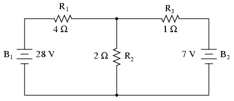
In Millman's Theorem, the circuit is re-drawn as a parallel network of branches, each branch containing a resistor or series battery/resistor combination. Millman's Theorem is applicable only to those circuits which can be re-drawn accordingly. Here again is our example circuit used for the last two analysis methods: ............

And here is that same circuit, re-drawn for the sake of applying Millman's Theorem: ............

By considering the supply voltage within each branch and the resistance within each branch, Millman's Theorem will tell us the voltage across all branches. Please note that I've labeled the battery in the rightmost branch as “B3” to clearly denote it as being in the third branch, even though there is no “B2” in the circuit!
Millman's Theorem is nothing more than a long equation, applied to any circuit drawn as a set of parallel-connected branches, each branch with its own voltage source and series resistance: ............

Substituting actual voltage and resistance figures from our example circuit for the variable terms of this equation, we get the following expression:

The final answer of 8 volts is the voltage seen across all parallel branches, like this:

The polarity of all voltages in Millman's Theorem are referenced to the same point. In the example circuit above, I used the bottom wire of the parallel circuit as my reference point, and so the voltages within each branch (28 for the R1 branch, 0 for the R2 branch, and 7 for the R3 branch) were inserted into the equation as positive numbers. Likewise, when the answer came out to 8 volts (positive), this meant that the top wire of the circuit was positive with respect to the bottom wire (the original point of reference). If both batteries had been connected backwards (negative ends up and positive ends down), the voltage for branch 1 would have been entered into the equation as a -28 volts, the voltage for branch 3 as -7 volts, and the resulting answer of -8 volts would have told us that the top wire was negative with respect to the bottom wire (our initial point of reference).
To solve for resistor voltage drops, the Millman voltage (across the parallel network) must be compared against the voltage source within each branch, using the principle of voltages adding in series to determine the magnitude and polarity of voltage across each resistor:

To solve for branch currents, each resistor voltage drop can be divided by its respective resistance (I=E/R):

The direction of current through each resistor is determined by the polarity across each resistor, not by the polarity across each battery, as current can be forced backwards through a battery, as is the case with B3 in the example circuit. This is important to keep in mind, since Millman's Theorem doesn't provide as direct an indication of “wrong” current direction as does the Branch Current or Mesh Current methods. You must pay close attention to the polarities of resistor voltage drops as given by Kirchhoff's Voltage Law, determining direction of currents from that.
............
Millman's Theorem is very convenient for determining the voltage across a set of parallel branches, where there are enough voltage sources present to preclude solution via regular series-parallel reduction method. It also is easy in the sense that it doesn't require the use of simultaneous equations. However, it is limited in that it only applied to circuits which can be re-drawn to fit this form. It cannot be used, for example, to solve an unbalanced bridge circuit. And, even in cases where Millman's Theorem can be applied, the solution of individual resistor voltage drops can be a bit daunting to some, the Millman's Theorem equation only providing a single figure for branch voltage.............
As you will see, each network analysis method has its own advantages and disadvantages. Each method is a tool, and there is no tool that is perfect for all jobs. The skilled technician, however, carries these methods in his or her mind like a mechanic carries a set of tools in his or her tool box. The more tools you have equipped yourself with, the better prepared you will be for any eventuality. ............
  • REVIEW:............
  • Millman's Theorem treats circuits as a parallel set of series-component branches.
  • All voltages entered and solved for in Millman's Theorem are polarity-referenced at the same point in the circuit (typically the bottom wire of the parallel network).............

Superposition Theorem Step By Step Procedure/Explanation

Superposition theorem is one of those strokes of genius that takes a complex subject and simplifies it in a way that makes perfect sense. A theorem like Millman's certainly works well, but it is not quite obvious why it works so well. Superposition, on the other hand, is obvious. .....:) :)
The strategy used in the Superposition Theorem is to eliminate all but one source of power within a network at a time, using series/parallel analysis to determine voltage drops (and/or currents) within the modified network for each power source separately. Then, once voltage drops and/or currents have been determined for each power source working separately, the values are all “superimposed” on top of each other (added algebraically) to find the actual voltage drops/currents with all sources active. Let's look at our example circuit again and apply Superposition Theorem to it:.....:) :)

Since we have two sources of power in this circuit, we will have to calculate two sets of values for voltage drops and/or currents, one for the circuit with only the 28 volt battery in effect. . . .....:) :)
.....:) :)
. . . and one for the circuit with only the 7 volt battery in effect:

When re-drawing the circuit for series/parallel analysis with one source, all other voltage sources are replaced by wires (shorts), and all current sources with open circuits (breaks). Since we only have voltage sources (batteries) in our example circuit, we will replace every inactive source during analysis with a wire.
Analyzing the circuit with only the 28 volt battery, we obtain the following values for voltage and current: .....:) :)


Analyzing the circuit with only the 7 volt battery, we obtain another set of values for voltage and current:
.....:) :)


.....:) :)
When superimposing these values of voltage and current, we have to be very careful to consider polarity (voltage drop) and direction (electron flow), as the values have to be added algebraically. .....:) :)

Applying these superimposed voltage figures to the circuit, the end result looks something like this:
.....:) :)
Currents add up algebraically as well, and can either be superimposed as done with the resistor voltage drops, or simply calculated from the final voltage drops and respective resistances (I=E/R). Either way, the answers will be the same. Here I will show the superposition method applied to current: .....:) :)

Once again applying these superimposed figures to our circuit:

Quite simple and elegant, don't you think? It must be noted, though, that the Superposition Theorem works only for circuits that are reducible to series/parallel combinations for each of the power sources at a time (thus, this theorem is useless for analyzing an unbalanced bridge circuit), and it only works where the underlying equations are linear (no mathematical powers or roots). The requisite of linearity means that Superposition Theorem is only applicable for determining voltage and current, not power!!! Power dissipations, being nonlinear functions, do not algebraically add to an accurate total when only one source is considered at a time. The need for linearity also means this Theorem cannot be applied in circuits where the resistance of a component changes with voltage or current. Hence, networks containing components like lamps (incandescent or gas-discharge) or varistors could not be analyzed.
Another prerequisite for Superposition Theorem is that all components must be “bilateral,” meaning that they behave the same with electrons flowing either direction through them. Resistors have no polarity-specific behavior, and so the circuits we've been studying so far all meet this criterion.
The Superposition Theorem finds use in the study of alternating current (AC) circuits, and semiconductor (amplifier) circuits, where sometimes AC is often mixed (superimposed) with DC. Because AC voltage and current equations (Ohm's Law) are linear just like DC, we can use Superposition to analyze the circuit with just the DC power source, then just the AC power source, combining the results to tell what will happen with both AC and DC sources in effect. For now, though, Superposition will suffice as a break from having to do simultaneous equations to analyze a circuit. .....:) :)
  • REVIEW:.....:) :)
  • The Superposition Theorem states that a circuit can be analyzed with only one source of power at a time, the corresponding component voltages and currents algebraically added to find out what they'll do with all power sources in effect.v
  • To negate all but one power source for analysis, replace any source of voltage (batteries) with a wire; replace any current source with an open (break)......:) :)

Thevenin's Theorem Step By Step Procedure

Thevenin's Theorem states that it is possible to simplify any linear circuit, no matter how complex, to an equivalent circuit with just a single voltage source and series resistance connected to a load. The qualification of “linear” is identical to that found in the Superposition Theorem, where all the underlying equations must be linear (no exponents or roots). If we're dealing with passive components (such as resistors, and later, inductors and capacitors), this is true. However, there are some components (especially certain ..... :)gas-discharge and semiconductor components) which are nonlinear: that is, their opposition to current changes with voltage and/or current. As such, we would call circuits containing these types of components, nonlinear circuits. ..... :)
Thevenin's Theorem is especially useful in analyzing power systems and other circuits where one particular resistor in the circuit (called the “load” resistor) is subject to change, and re-calculation of the circuit is necessary with each trial value of load resistance, to determine voltage across it and current through it. Let's take another look at our example circuit:..... :)

Let's suppose that we decide to designate R2 as the “load” resistor in this circuit. We already have four methods of analysis at our disposal (Branch Current, Mesh Current, Millman's Theorem, and Superposition Theorem) to use in determining voltage across R2 and current through R2, but each of these methods are time-consuming. Imagine repeating any of these methods over and over again to find what would happen if the load resistance changed (changing load resistance is very common in power systems, as multiple loads get switched on and off as needed. the total resistance of their parallel connections changing depending on how many are connected at a time). This could potentially involve a lot of work!
Thevenin's Theorem makes this easy by temporarily removing the load resistance from the original circuit and reducing what's left to an equivalent circuit composed of a single voltage source and series resistance. The load resistance can then be re-connected to this “Thevenin equivalent circuit” and calculations carried out as if the whole network were nothing but a simple series circuit:

. . . after Thevenin conversion . . .

The “Thevenin Equivalent Circuit” is the electrical equivalent of B1, R1, R3, and B2 as seen from the two points where our load resistor (R2) connects.
The Thevenin equivalent circuit, if correctly derived, will behave exactly the same as the original circuit formed by B1, R1, R3, and B2. In other words, the load resistor (R2) voltage and current should be exactly the same for the same value of load resistance in the two circuits. The load resistor R2 cannot “tell the difference” between the original network of B1, R1, R3, and B2, and the Thevenin equivalent circuit of EThevenin, and RThevenin, provided that the values for EThevenin and RThevenin have been calculated correctly.
The advantage in performing the “Thevenin conversion” to the simpler circuit, of course, is that it makes load voltage and load current so much easier to solve than in the original network. Calculating the equivalent Thevenin source voltage and series resistance is actually quite easy. First, the chosen load resistor is removed from the original circuit, replaced with a break (open circuit):

Next, the voltage between the two points where the load resistor used to be attached is determined. ..... :)Use whatever analysis methods are at your disposal to do this. In this case, the original circuit with the load resistor removed is nothing more than a simple series circuit with opposing batteries, and so we can determine the voltage across the open load terminals by applying the rules of series circuits, Ohm's Law, and Kirchhoff's Voltage Law: ..... :)


The voltage between the two load connection points can be figured from the one of the battery's voltage and one of the resistor's voltage drops, and comes out to 11.2 volts. This is our “Thevenin voltage” (EThevenin) in the equivalent circuit:

To find the Thevenin series resistance for our equivalent circuit, we need to take the original circuit (with the load resistor still removed), remove the power sources (in the same style as we did with the Superposition Theorem: voltage sources replaced with wires and current sources replaced with breaks), and figure the resistance from one load terminal to the other: ..... :)

With the removal of the two batteries, the total resistance measured at this location is equal to R1 and R3 in parallel: 0.8 Ω. This is our “Thevenin resistance” (RThevenin) for the equivalent circuit: ..... :)

With the load resistor (2 Ω) attached between the connection points, we can determine voltage across it and current through it as though the whole network were nothing more than a simple series circuit:

Notice that the voltage and current figures for R2 (8 volts, 4 amps) are identical to those found using other methods of analysis. Also notice that the voltage and current figures for the Thevenin series resistance and the Thevenin source (total) do not apply to any component in the original, complex circuit. Thevenin's Theorem is only useful for determining what happens to a single resistor in a network: the load.
The advantage, of course, is that you can quickly determine what would happen to that single resistor if it were of a value other than 2 Ω without having to go through a lot of analysis again. Just plug in that other value for the load resistor into the Thevenin equivalent circuit and a little bit of series circuit calculation will give you the result. ..... :)
  • REVIEW:..... :)
  • Thevenin's Theorem is a way to reduce a network to an equivalent circuit composed of a single voltage source, series resistance, and series load...... :)
  • Steps to follow for Thevenin's Theorem:..... :)
  • (1) Find the Thevenin source voltage by removing the load resistor from the original circuit and calculating voltage across the open connection points where the load resistor used to be.
  • (2) Find the Thevenin resistance by removing all power sources in the original circuit (voltage sources shorted and current sources open) and calculating total resistance between the open connection points...... :)
  • (3) Draw the Thevenin equivalent circuit, with the Thevenin voltage source in series with the Thevenin resistance. The load resistor re-attaches between the two open points of the equivalent circuit.
  • (4) Analyze voltage and current for the load resistor following the rules for series circuits...... :)

Norton's Theorem Step By Step Procedure

Norton's Theorem states that it is possible to simplify any linear circuit, no matter how complex, to an equivalent circuit with just a single current source and parallel resistance connected to a load. Just as with Thevenin's Theorem, the qualification of “linear” is identical to that found in the Superposition Theorem: all underlying equations must be linear (no exponents or roots).
Contrasting our original example circuit against the Norton equivalent: it looks something like this:

. . . after Norton conversion . . .

Remember that a current source is a component whose job is to provide a constant amount of current, outputting as much or as little voltage necessary to maintain that constant current.
As with Thevenin's Theorem, everything in the original circuit except the load resistance has been reduced to an equivalent circuit that is simpler to analyze. Also similar to Thevenin's Theorem are the steps used in Norton's Theorem to calculate the Norton source current (INorton) and Norton resistance (RNorton).
As before, the first step is to identify the load resistance and remove it from the original circuit:

Then, to find the Norton current (for the current source in the Norton equivalent circuit), place a direct wire (short) connection between the load points and determine the resultant current. Note that this step is exactly opposite the respective step in Thevenin's Theorem, where we replaced the load resistor with a break (open circuit):

With zero voltage dropped between the load resistor connection points, the current through R1 is strictly a function of B1's voltage and R1's resistance: 7 amps (I=E/R). Likewise, the current through R3 is now strictly a function of B2's voltage and R3's resistance: 7 amps (I=E/R). The total current through the short between the load connection points is the sum of these two currents: 7 amps + 7 amps = 14 amps. This figure of 14 amps becomes the Norton source current (INorton) in our equivalent circuit:

Remember, the arrow notation for a current source points in the direction opposite that of electron flow. Again, apologies for the confusion. For better or for worse, this is standard electronic symbol notation. Blame Mr. Franklin again!
To calculate the Norton resistance (RNorton), we do the exact same thing as we did for calculating Thevenin resistance (RThevenin): take the original circuit (with the load resistor still removed), remove the power sources (in the same style as we did with the Superposition Theorem: voltage sources replaced with wires and current sources replaced with breaks), and figure total resistance from one load connection point to the other:

Now our Norton equivalent circuit looks like this:

If we re-connect our original load resistance of 2 Ω, we can analyze the Norton circuit as a simple parallel arrangement:

As with the Thevenin equivalent circuit, the only useful information from this analysis is the voltage and current values for R2; the rest of the information is irrelevant to the original circuit. However, the same advantages seen with Thevenin's Theorem apply to Norton's as well: if we wish to analyze load resistor voltage and current over several different values of load resistance, we can use the Norton equivalent circuit again and again, applying nothing more complex than simple parallel circuit analysis to determine what's happening with each trial load.
  • REVIEW:
  • Norton's Theorem is a way to reduce a network to an equivalent circuit composed of a single current source, parallel resistance, and parallel load.
  • Steps to follow for Norton's Theorem:
  • (1) Find the Norton source current by removing the load resistor from the original circuit and calculating current through a short (wire) jumping across the open connection points where the load resistor used to be.
  • (2) Find the Norton resistance by removing all power sources in the original circuit (voltage sources shorted and current sources open) and calculating total resistance between the open connection points.
  • (3) Draw the Norton equivalent circuit, with the Norton current source in parallel with the Norton resistance. The load resistor re-attaches between the two open points of the equivalent circuit.
  • (4) Analyze voltage and current for the load resistor following the rules for parallel circuits.
Like us on Facebook
Follow us on Twitter
Recommend us on Google Plus
Subscribe me on RSS